3 Phase Motor Control Panel Wiring Diagram
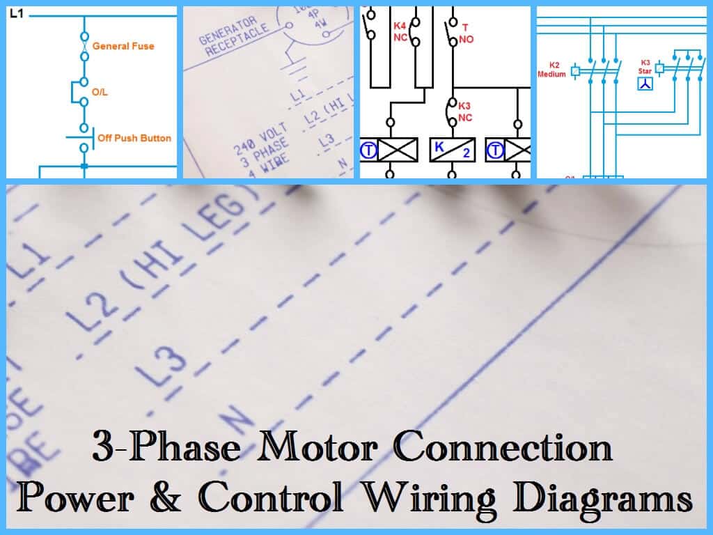
208v single phase and 3 distribution board wiring electrical panel detail submersible pump microcontroller what is three electric motor diagram sensor load circuit number colors stp cb 5 control general line for cur transformer electricity meter fo 4. Three phase motor connection schematic, power and control wiring installation diagrams.
three phase dol starter Control overload Indicator Power Wiring diagram YouTube
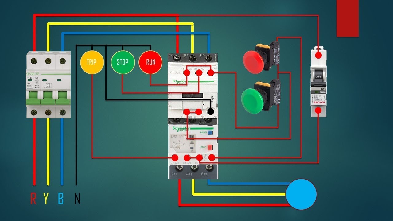
Diagram 208 120v 3 phase wire full version hd quality outletdiagram newsymposium it.
3 phase motor control panel wiring diagram. 480v 3 phase motor wiring diagram effectively read a cabling diagram one has to learn how typically the components in the system operate. Three phase motor connection schematic, power and control wiring installation diagrams. The three phases are then connected to a power interrupter.
I am not sure how much knowledge you have in electrical reading, but in short i can supply you with a few diagrams for 3phase motor control. U can easily understand the working of 3 phase circuit here. Submersible pump control box wiring diagram for 3 wire single phase submersible pump submersible well pump submersible.
An example of a wiring diagram for a motor controller is shown in figure 1. Electrical diagrams motor phase pump with manual automatic float court in 2020 diy electrical basic electrical wiring electrical wiring. However, the actual contents vary widely as per requirements.
Dashed lines indicate a single purchased component. Motor control panel wiring diagram pdf wiring diagram is a simplified within allowable limits pictorial representation of an. The original wiring diagram showed the proper arrangement of windings to create a larger wye system in which there are four equal windings between any two leads.
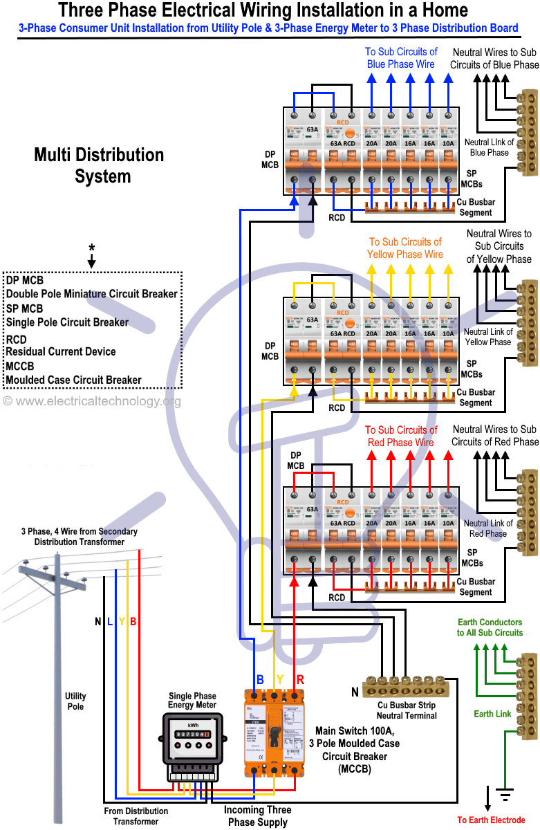
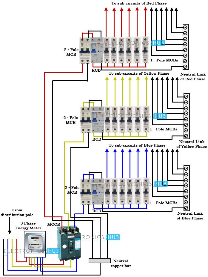
Phase controller wiring phase failure relay diagram relay electrical panel wiring failure. Single phase variable frequency drive vfd circuit (with. 3 phase distribution panel electrical circuit diagram electricity home electrical wiring
The first step is to figure out the voltage of your phases. R , y, b = red, yellow, blue ( 3 phase lines)c.b = general circuit breakermain = mai supplyy = starδ = deltac1, c2, c3 = contatcors (power diagram)o/l = over load relayno = normally opennc = normally closed k1 = contactor (contactor coil) k1/no = contactor. Three phase slip ring rotor starter control power power electric circuit electricity magnetism.
From the diagram one can see that the power source for the vfd is provided at terminals r. The below wiring diagram shows how we would assemble a complete motor starter, with a start/stop button for. I figure, they are wdeliy available so i might as well make use of them.
Your email address will not be. Pretty 480 delta wiring diagram contemporary electrical circuit and 480v 3 phase diagram electrical diagram electrical wiring diagram. Typical wiring diagram line diagrams show circuits of the operation of the controller.
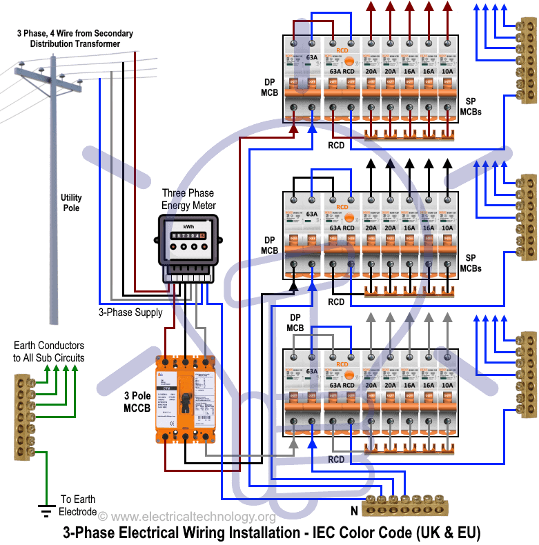
Below three phase distribution board wiring diagram shown. Water pump controller with float switchauto manual connection of water pump motor w. In the united states, for low voltage motors (below 600v), you can expect either 230v or 460v.
Now in the below diagrams, three phase motor will rotate in two directions viz forward and reverse. Then you connect the 2 motor leads to t1 and t3. Note that symbols are discussed in detail later).
Three phase motor connection reverse and forward power and control wiring diagrams (two direction one speed) abbreviations:o/l = over load relayno = normally opennc = normally closerev = reverse for =. Both line and wiring diagrams are a language of pictures. Marathon electric motor wiring diagram electric motor marathon electric diagram.
Three phase motor power & control wiring diagrams this is a 3 phase motor control circuit. Control wiring unique control wiring basics data wiring. Cur transformer electricity meter wiring diagram kilowatt hour three phase electric power png clipart angle area.
Using this method, the current is balanced between the 3 poles on the overload. Based on your observations of these two diagrams explain how electromechanical relays are represented differently between ladder and schematic diagrams. I’m also throwing in a bunch of monolithic transistors in case i feel the need to build one instead.
The contacts, m, will be controlled by the coil, m.the output of the motor starter goes to a three phase ac motor. Mastering motor control center (mcc): It includes guidelines and diagrams for different kinds of wiring methods along with other products like lights, windows, and so.
That being said, there is a wide range of different motors and what you have on hand can be completely different. Collection of duplex pump control panel wiring diagram. Make sure that the voltage you will be.
The circuit breaker has a handle that goes through the door to. This system uses 3 phase ac power (l1, l2 and l3) connected to the terminals. Wiring diagrams and equipment from zero to hero.
Pin on electrics electronics

Wiring Diagram Panel Motor 3 Phase gewinnspielcisa

Three Phase Motor Power & Control Wiring Diagrams
Wiring Diagram Panel Motor 3 Phase gewinnspielcisa

Diagrams 2 Electrical And Electronics Learning Blog

Pin on vinod

Subpanel / RPC panel / 3 Phase Load Center Wiring

3 Phase Motor Wiring Diagrams NonStop Engineering Electronic Pinterest Diagram

3 Phase Motor Control Wiring Tutorial Rig Electrician Training YouTube

Star Delta Motor Starter Connection Diagram three phase motor Electrical circuit diagram

️ Basic circuit diagram of a 3 phase motor 😊 Save and share this post. Tag your friends

3 phase panel hook up new to 3 phase 208v. 20200312
3 Phase To Single Phase Wiring Diagram Cadician's Blog
Image result for how to commission a three phase poshomily Electrical circuit diagram, Home

Electrical and Electronics Engineering Types of Motor Control Schematics!! Electrical circuit

Wiring Diagram For Motor Starter 3 Phase Controller Failure Relay Electrical Pleasing Three And

Wiring Diagram 3 Phase Contactor

Wiring Diagram Panel Motor 3 Phase gewinnspielcisa
480v 3 Phase Reversing Motor Starter Wiring Diagram
